
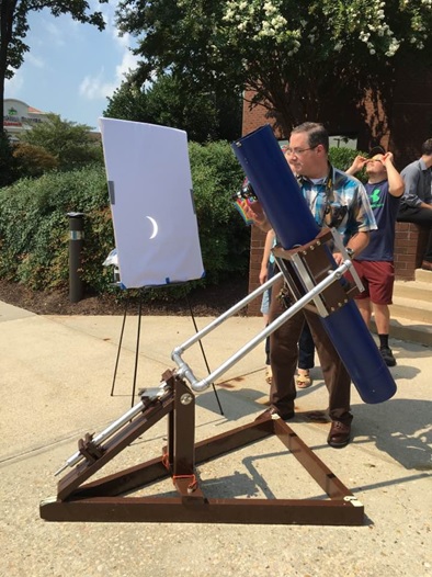
during the last total solar eclipse, August 21st, 2017.
A Different Take on The Classic First Telescope
The venerable 6″ f/8 telescope is often suggested as the ideal first telescope. Far and away the 6″ f/8 is much better than the department store refractor. Here is the story behind why I chose to start with this telescope in 1980, and what I’ve learned about telescope making along the way.
- The 6″ f/8 is a powerful telescope. Period. This scope can pull in the planets and can provide enough magnification to get outstanding views of the gas giants, with sharp bands on Jupiter, the Jovian moons, the rings of Saturn, and even detail on Mars during favorable oppositions, like this years one.
- The 6″ f/8 is also a versatile telescope, enabling not over-wide but still quite pleasant views of all of the Messier and many Caldwell and NGC objects.
- It is not too heavy or unwieldy for a youth to move, store or transport.
- The 6″ f/8 is also an affordable telescope, the primary mirror and matched 1.83″ secondary were obtained from Coulter Optical for $79 in 1981. Today they can be obtained for $130.50 from Agena Astro.
- The pipe-fitting fork mount is also inexpensive to build, involving lumber and hardware that is easily obtainable from home stores.
- If you look at the telescope I constructed above, you’ll see that the entire telescope is within the skill of a 16 year old who has had a basic woodshop industrial arts class. I know, because that’s how old I was when I built this telescope in it’s first iteration.
Inspiration: In the 1979-1980 school year I entered high school, and my science instructor for general science, Mr. Carlton Meyers, took an interest in me. Perhaps it was my curiosity and passion for all things scientific. Perhaps it was the launch of Carl Sagan’s “Cosmos” on PBS. Whatever the reason, Mr. Meyers “checked out” a 4.25″ Criterion on a non-driven German Equatorial Mount from Mr. O’Reilly, the Planetarium Director at Williamsville North High School, and loaned the telescope to me for three months during the summer of 1980. That year was “The Great Conjunction” for about 6 months we could see Mercury, Venus, Mars, Jupiter and Saturn all in about a 120 degree area of the sky. I struggled with that “GEM” and was hooked on Astronomy, and had a love-hate relationship with the Newtonian Reflector. I loved the mirror/eyepiece system of the Newtonian, and I hated the constant meridian flipping of the flipping GEM mount. Not a fan…
That Christmas, my parents, wanting to fuel my astronomical interests (before STEM was a thing), purchased for me a 6″ telescope mirror grinding kit. I had a 6″ diameter 1″ thick Pyrex mirror blank, a 5.75″ plate glass “tool”, a bundle of abrasives for grinding, rouge for polishing, and even a pack of pine pitch for melting to pour a “pitch lap.” Today you can get a similar kit from Willman-Bell, mine was from Edmund Scientific, and I ground my mirror following instructions in Edmund’s book by Sam Brown–“All About Telescopes.” I spent all of that Christmas break “pushing glass” in my parent’s basement, and I learned a lot about optics and how precise a curve one can develop just by following the expertise in a book. It didn’t take long to get an f/10 curve in rough grinding, and then shape it down to an f/9 in fine grinding. I got the mirror polished and figured and it, but then came the issue of aluminizing.
I sent out letters for quotes on the aluminizing process, and found out it would have cost twice as much to have my mirror aluminized as it would have to just purchase one from Coulter Optical in California. So in June of 1981 I ordered a mirror set from Coulter and received the pair in November of that year.
Optical Tube Assembly:
My telescope’s first tube was a 6″ schedule 40 PVC sewer pipe–I designed a primary mirror cell that fit into the flare at the bottom end of the tube, and planned on 100% of the light coming down the tube to strike the mirror, not realizing that I was unnecessarily vignetting the mirror, and that the scope would have benefited from being another inch in diameter wider than the mirror itself. [This was in the days before the Internet, and I didn’t have “Newt-Web” available during my telescope design.] What I did have was paper grocery sacks, which I could cut along the corners, and tape two bags together to get a sheet of brown paper long enough to do a full-scale ray trace diagram, the diagram was important because that enabled me to measure where to drill the hole in the tube for the Edmund 1.25″ rack and pinion focuser. The diagram worked like a champ and I was able to drill the tube the first time with success, and got the focuser installed, this first iteration had a single stalk secondary mirror holder.
Another significant upgrade was using self-stick flocking paper from Scopestuff.com–this significantly increased the contrast in the eyepiece over using flat black spray paint, as I had in the original PVC pipe.
Secondary Holder: The 1.83″ minor axis secondary was glued to a sheet of blotter paper, which was in turn glued to a 1-1/4″ diameter PVC pipe section 2″ long and cut at a 45 degree angle to create the angular offset for the mirror surface. The PVC pipe was epoxied to a maple hardwood washer and that had a 3/8″ bolt passed through it with the head hidden behind the mirror. The bolt itself was drilled through the side with a 3/16″ drill to create a receptacle for the down rod from the focuser. The down-rod was bent toward the front of the telescope and then back parallel to the eyepiece holder to get the center of the mirror directly under the eyepiece and at the proper vertical offset in the tube so that the secondary was properly collimated. The down-rod was connected to the secondary-bolt by sandwiching it between two nuts that were then tightened. It was very simple, but also all that was required. The down rod attached to the eyepiece focuser with a single slotted screw.
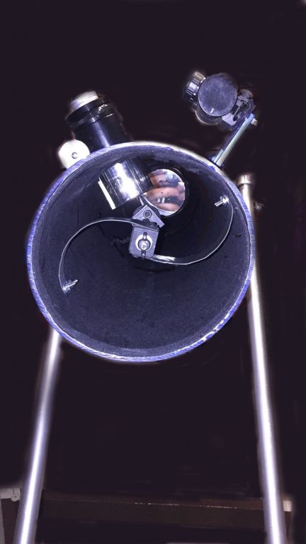
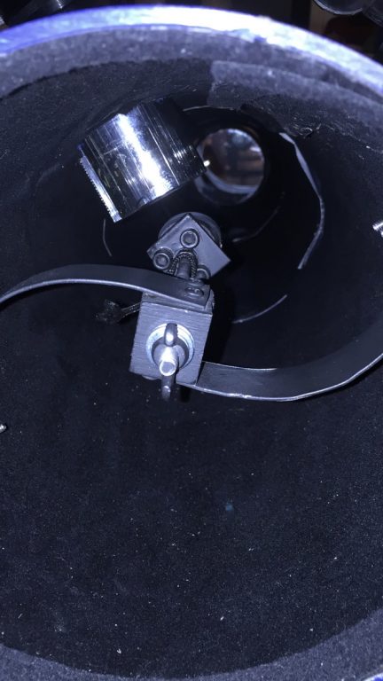
On the 2017 rebuild, I had a 2″ diameter Orion rack and pinion focuser that I wanted to use, and that upgrade forced a re-design on the secondary spider as well–I built a double curved arm spider by bending 1/16″ thick by 1″ wide aluminum bar stock around a 9″ diameter wood circle to get two overlapping arcs that are bolted to the inside of the tube, and screwed to a wood block which holds the secondary. The secondary backing plate is a square of aluminum which is held to a wood dowel via three springs on 1/4 20 socket head screws so that collimation can be adjusted via an Allen key.
Primary Mirror Cell: The Sam Brown book provided clear instruction on how to make a very simple primary mirror cell. Collimation is obtained by adjusting the three wing nuts that adjusted the tension on the springs between the plate attached to the tube, which I’d made from a discarded solid maple end table, and the plywood disc behind the mirror. The two plates were joined by 3 carriage bolts set at 120 degrees apart from each other and 2/3rds of the way out from the center of the primary mirror. The primary was held to the plywood disk using three sheet metal clips which were screwed to the plywood using wood screws and washers, simple and rigid. Between the two plates of the cell were three stiff springs capable of holding about 25 PSI each, which was overkill for a primary mirror weighing less than 5 pounds, but that stiffness ensured that the telescope always held collimation.
The Mounting:
The Cradle:
The cradle assembly again was simplicity itself. To make the upper cradle arms, I selected 12″ long sections of scrap 2″ x 4″ for the top, and 12″ long sections of scrap 2″ x 6″ for the bottom. I placed these together and traced out a 6-1/2″ diameter circle across the two boards and then raised the foot on our jig saw to cut out the arcs from the two boards so that the boards could receive the telescope tube. The boards were then attached on the east side by having a 4″ tall, 12″ wide section of 5/8″ plywood screwed to the top edge of the 2″ x 6″ These two side boards were eventually drilled through and bolted to the fork arms at the center of balance vertically and horizontally with a 3/8″ bolt. the inside of the plywood was also fitted with a heavy galvanized washer with a 3/8″ diameter center hole, and screwed with 1/2″ long #6 flat head wood screws to create a metal bushing for the declination axis to spin on. The outer perimeter of the cradle was constructed of four 1 foot long sections of 1/16″ thick 1″ x 1″ angle aluminum these sections were pre drilled for 1″ long #10 round headed wood screws offset by 3/8’s of an inch from each other and 1/2 inch from the edge. When I rebuilt the telescope in 2017 I replaced the original slot headed screws with stainless steel flat headed screws. I also upgraded the screws in the plywood with 1-1/2″ number 10 pan headed stainless screws with decorative brass washers to class up the mount.
To create sufficient tension on the tube, the inside of the boards are contact cemented to open-cell foam 1″ thick, which compresses down creating sufficient clamping pressure on the tube. In my most recent rebuild I also used four 2″ diameter super-slider foam/felt pads stapled with my air nailer to the 2″ x 6″ bottom board, with the felt side facing the tube.
New Tube: The tube in these pictures is a 7″ diameter bollard cover from PostGuard.com With shipping the tube cost less than $100. I see the current price ($39.95) are actually less than what I remember paying two years ago.
The cradle is hinged with normal fixed pin hinges 1-5/8″ wide on the east side of the mount, screwed into the 2″ x 4″ and 2″ x 6.” On the west side, the scope is closed using two hasp and staples, with the hasp attached to the top, and the staple attached to the bottom. When the hasp is strapped down, a deadbolt, standing on washers to offset it above the height of the staple, is drawn across the hasp bar to hold it in place and lock it closed. One deadbolt is used on either end of the cradle to hold the telescope tube in place, balanced front to back. simply loosening the deadbolts is all that is needed in order to rotate the tube during use, enabling the eyepiece to be placed in a comfortable position at all times. The scope is designed so that the eyepiece is at eye height for me (I’m 5′ 10″ tall) at about 5′ 7″ above the ground when the telescope is pointed at the zenith–straight overhead. This ensures that other adults almost never need a ladder with this telescope.
The Base:
The original platform base was constructed of 2″ x 4″ arranged in a triangle with the flat sides on the ground and a Redwood box to which the bearing pillow blocks were lag screwed. The platform base was re-designed to it’s present configuration in 1990 so that it could be collapsed and folded up to fit in the back of any compact car with 5′ of linear trunk space.
This new design breaks the telescope down into five sub-components: The Optical-Tube Assembly (OTA), the base assembly, the cross-spar, the vertical upright, and the cradle/fork arm assembly. We have already discussed the OTA and the cradle. The Fork itself is composed of 1-1/4″ diameter (OD) galvanized pipe fittings–two caps, two 30″ arms, 2 90 degree elbows, 2 6″ long nipples and a tee. The Tee threads on and off to separate the cradle/fork arm assembly from the base assembly.
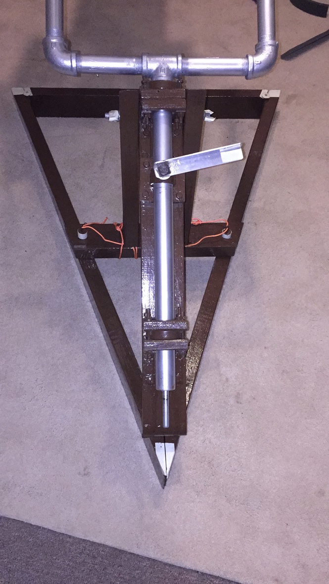
The Base Assembly: The base assembly is comprised of three sections of 2″ x 4″ the two triangle legs, which were cut on a 20 degree angle to form a 40 degree base angle for the isosceles base–it is a 40-70-70 angle triangle with 54 inch sides and a 32 inch wide base below the fork arms. Key to the construction and the rigidity and mobility of the design are four loose-pin hinges.
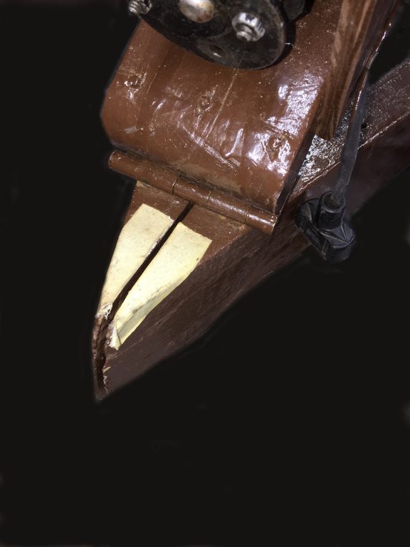
At the south end of the triangular frame, the two legs with the two-by-fours stood on edge, were mitered at a 20 degree angle, so that when wedged together, they form a 40 degree angle on the outside of the frame. At the top of the miter, I placed a loose pin hinge, screwing each side to one of the two by fours.
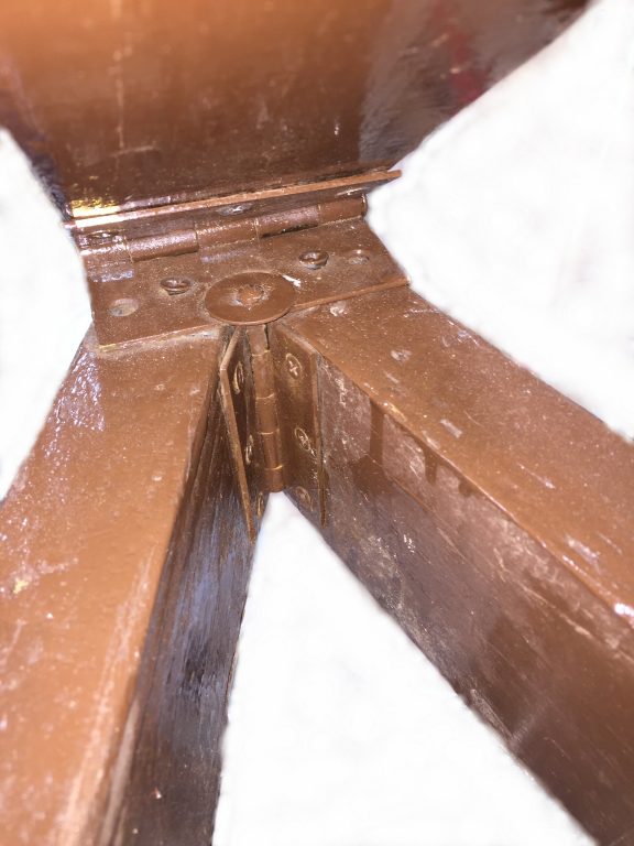
The polar axis support is a 28″ length of two by four, the south end of which is sanded round in profile, and it also is hinged to the base in a clever manner–there is one half of the polar axis’s hinge screwed to the 2 x 4. The other half is attached by passing the pin for the base’s vertically-oriented hinge through the center screw hole of the horizontal hinge for the polar axis shaft. The other two screws for the bottom plate of the polar axis shaft go into the center of the top edges of each of the 2 x 4’s but are deliberately left just loose enough to facilitate folding the entire mechanism up, so that the legs of the triangle can come together and when the hinge pins of the triangle base are removed.
Two fender washers are placed on the hinge pins of the cross spar to enable tool-less assembly and disassembly. The washers and corners of the mounting are all marked with glow-in-the-dark duct tape. This is for safety as most public viewers aren’t familiar with this style of mounting.
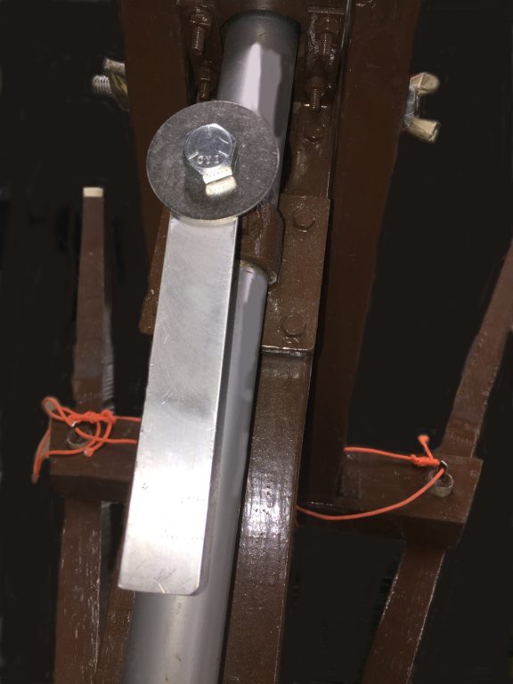
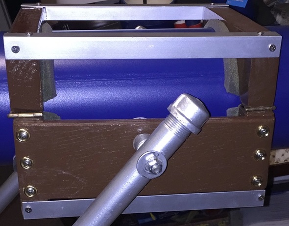
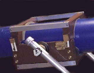
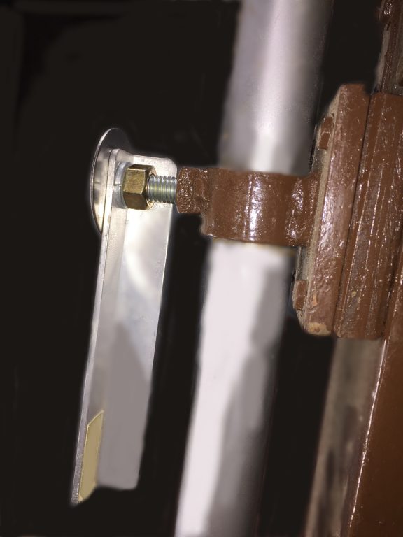
The braking mechanism for the polar axis is a simple mechanism–a 2″ inside diameter ring has a 1/2 inch-13 thread nut welded to it, and the ring itself is welded to a 3-1/2″ square of 1/4″ boilerplate, which is lag screwed to the 2×4 polar axis arm with 1″ lag bolts. The lever is a 6″ length of 1×1 angle aluminum bolted to a 2″ long 1/2″-13 bolt–see the photo below:
The polar axis support arm is held up by a base plate spanning the base triangle and held in position very simply using two 7/8″ diameter locator pegs that pass straight through the flat of the base plate and to half the depth of the 2×4 making up the base triangle legs:
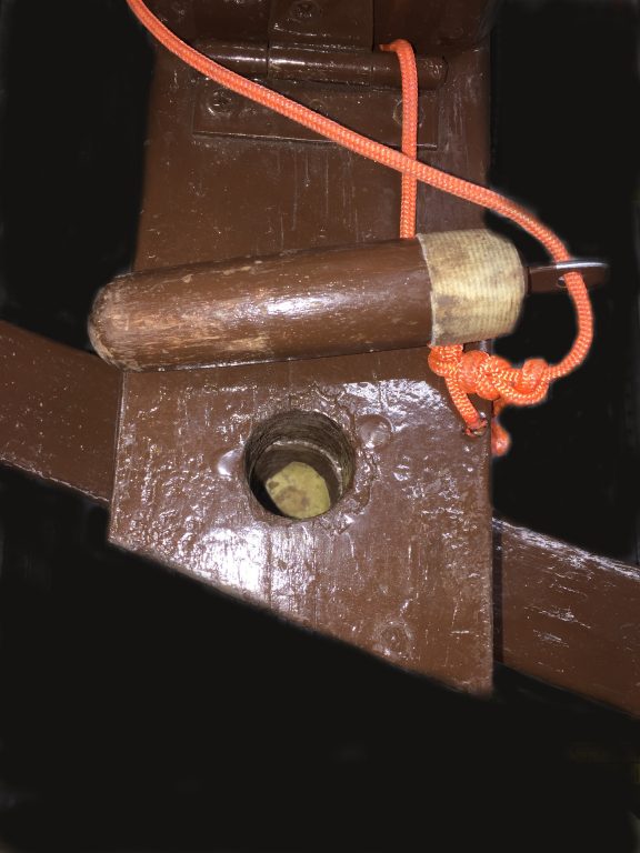
Note the pegs have retaining loops and are permanently attached to the scope using orange parachute cord to keep them with the upright support even when the upright is removed for transportation. The pegs function just fine, and they serve only to keep the vertical upright in the vertical position, since gravity is holding the fork over the upright, there is no need to bolt the crosspiece in place. The glow-in-the-dark duct tape helps find the pegs and to align the holes in the dark. Note the glow tape at the bottom of the base triangle leg’s 1″ diameter hole.
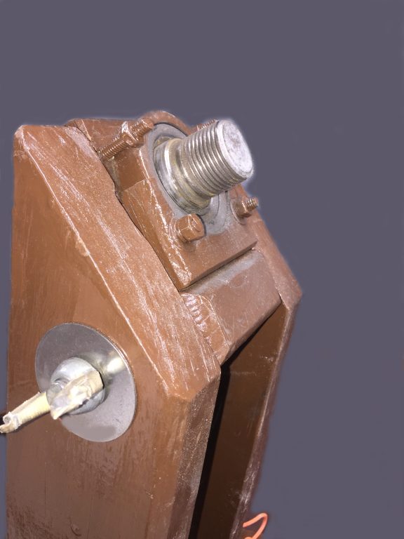
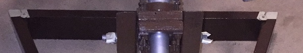
The upright support arms are cut at a 40 degree down angle so they do not block the swing of the fork as it rotates in right ascension. The two arms sandwich the polar axis support arm, and a 1/2″ diameter 10″ long section of all thread passes through the assembly and two stainless washers. Two wing-nuts with glow tape make for a rapid and tool-less assembly that is very rigid once the locator pins have been inserted and the wing-nuts are hand tightened. This photo also shows the 1-1/4″ pipe threads that were machined into the head of the 1-1/2″ solid steel shaft
Motor Drive:
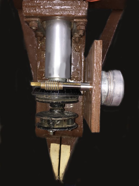
The latest addition to the telescope is the implementation of an Edmund Scientific 1/2″ diameter drive gear and worm wheel set that were purchased for me by my parents back in the 1980s. The worm’s drive shaft size is 3/16″, and the worm is driven by a brand new Hurst Synchron(R) 115VAC 1/15th RPM (4 RPH) Motor I purchased from Herbach & Rademan in New Jersey. There are also two of this same motor on my VNS Equatorial Platform.
The worm wheel is held to the telescope by friction exerted by a friction clutch that consists of three small floor flanges, the top one is screwed to a solid, round wood block that is checkered and is capped by a circle of suede leather which is applied to the inside of the RA Circle. Above the RA Circle is another donut of suede leather and there is a third circle of suede between the worm wheel and the two spacer washers above it that hold the gear in alignment with the motor drive. Below the top floor flange, are two other floor flanges, the bottom of which is screwed with three set screws to the 6″ long 1/2″ tool-steel shaft that was machined and hydraulically press-fit into the end of the 1-1/2″ Polar Axis shaft. Tension is adjusted by loosening three bolts enabling three springs to apply increased tension to the worm wheel. This design enables the scope to be slipped to an object in RA, and then the motor drive will hold the object in the eyepiece once the telescope is let go.
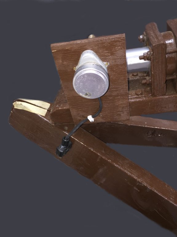
The Hurst Synchron (R) motor design with it’s planetary gearing and high shaft power and low stall rate is a proven technology having been in continuous service since it was first invented in 1929. It works beautifully whether plugged in to mains or when run off a high-quality ACDC inverter plugged into my battery. At this point I have not implemented any speed control yet, but may add a rheostat to enable the scope to track at lunar or planetary rates, but for now this drive has shown itself to be adequate at magnifications up to 150x, with only minor visible drift which could be attributable to polar alignment as much as the motor speed.
A tour de force sir! I enjoyed reading about your ATM journey here.